Understanding the Dielectric Constant of FR4 Substrate in PCB
FR4 is one of the most widely used materials in printed circuit board (PCB) manufacturing due to its excellent mechanical strength, cost-effectiveness, and electrical insulation properties. It is a composite material consisting of woven glass fiber and epoxy resin, making it ideal for a variety of electronic applications. However, understanding the dielectric constant of FR4 is crucial for achieving optimal PCB performance, particularly in high-speed and high-frequency designs. The dielectric constant directly influences signal propagation speed and impedance control, making it a key factor in ensuring signal integrity. Variations in the dielectric constant of FR4 substrate across different frequencies can lead to signal loss and degraded performance, especially in advanced applications. This article will focus on explaining the dielectric constant of FR4, its behavior over varying frequencies, and its impact on PCB design, helping designers make informed material selections for their electronic projects.
What is FR4 Material and Dielectric Constant of FR4 Substrate?
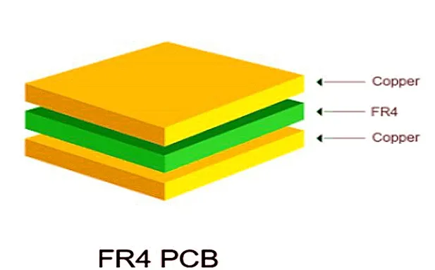
FR4 is a widely used composite material in printed circuit board (PCB) manufacturing. It is composed of woven glass fiber fabric and epoxy resin, which together create a strong, durable, and reliable substrate. The name “FR4” stands for Flame Retardant Level 4, indicating its excellent fire resistance, which is a key requirement in electronics.
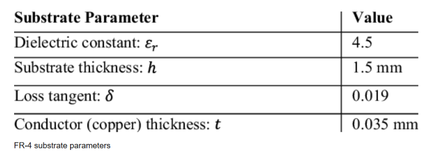
One of the critical characteristics of FR4 is its versatility, making it a preferred choice for PCB fabrication. The dielectric constant of FR4 substrate typically ranges between 4.3 to 4.7, depending on the frequency and material thickness. This property plays a significant role in determining signal integrity, as it impacts the speed of signal propagation across the PCB.

Key Properties of FR4
- High Mechanical Strength: FR4 offers robust structural integrity, allowing it to withstand mechanical stress.
- Good Thermal Resistance: It performs well under varying thermal conditions, maintaining stability during operation.
- Cost-Effectiveness: FR4 is affordable compared to advanced substrates, making it ideal for mass production.
Common Applications
FR4 is widely used in general-purpose PCBs for consumer electronics, such as home appliances, toys, and computing devices. Additionally, it is well-suited for low-frequency circuit boards, where signal loss and high-speed performance are not primary concerns. However, for more advanced applications, understanding the dielectric constant of FR4 substrate is crucial, as it directly affects the overall performance and reliability of the PCB.
Get a Quotation For Dielectric Donstant of Fr4 Substrate Now
What is Dielectric Constant and Why Does It Matter in Dielectric Constant of FR4 Substrate?
The dielectric constant of FR4 substrate is a fundamental property that defines how well the material can store electrical energy when subjected to an electric field. Also referred to as Dk or relative permittivity, the dielectric constant measures the ability of an insulating material, like FR4, to hold charge relative to a vacuum. In FR4, this value typically falls within the range of 4.3 to 4.7, but it can vary depending on factors such as frequency, manufacturing process, and specific laminate structure. Understanding the dielectric constant is essential for evaluating how FR4 performs in different PCB applications, especially in high-speed designs where signal integrity is critical.
Importance of the Dielectric Constant of FR4 Substrate
Understanding the dielectric constant of FR4 substrate is essential because it directly influences the performance of a PCB, particularly in high-speed and high-frequency designs:
- Signal Propagation Speed:
A higher dielectric constant reduces the speed at which signals travel through the substrate. This happens because the electric field interacts more with the material, delaying signal propagation. For FR4, a relatively high dielectric constant means it is suitable for low-frequency applications but less optimal for high-speed circuits. - Signal Integrity:
The stability of the dielectric constant of FR4 substrate is crucial for maintaining signal integrity. Variations in Dk can lead to impedance mismatches, signal loss, and signal distortion, particularly in high-frequency or RF designs. Designers must account for these variations to ensure consistent PCB performance.
The dielectric constant of FR4 substrate plays a vital role in PCB design by influencing signal speed and integrity. For advanced applications like RF, microwave, or high-speed digital circuits, understanding and managing the dielectric constant is key to optimizing overall performance.

Dielectric Constant of FR4 vs Frequency in Dielectric Constant of FR4 Substrate
The dielectric constant of FR4 substrate is not a fixed value but changes depending on the frequency of the signal passing through it. This behavior is particularly important in modern PCB designs, where high-frequency signals are increasingly common.
Behavior of the Dielectric Constant of FR4 Substrate Across Frequencies
At low frequencies, the dielectric constant of FR4 substrate remains relatively stable, typically within the range of 4.3 to 4.7. This stability makes FR4 an effective and reliable choice for general-purpose and low-frequency circuit boards. However, as the frequency increases, the dielectric constant begins to decrease. At high frequencies, this reduction in Dk can lead to increased signal loss and attenuation, affecting the overall performance of the PCB. This is because higher frequencies cause more energy interaction with the substrate, making signal propagation slower and less efficient.
Practical Impact
For high-speed digital or RF circuits, variations in the dielectric constant of FR4 substrate can pose significant challenges:
- Impedance Matching: Changes in the dielectric constant impact the characteristic impedance of PCB traces, which can lead to signal reflection and poor signal integrity.
- Performance: As frequencies increase, higher signal losses and attenuation can degrade the PCB’s ability to maintain clean, accurate signals.
FR4 vs Other Materials
While FR4 is cost-effective and widely used, it may not be ideal for high-frequency applications. In comparison, materials like Rogers 5880 have a much lower dielectric constant (approximately 2.2) and offer better performance at high frequencies. These low-Dk materials minimize signal loss, reduce propagation delays, and maintain consistent performance across a wide range of frequencies.
While the dielectric constant of FR4 substrate is suitable for low-frequency designs, its frequency-dependent behavior makes it less favorable for high-speed or RF applications compared to advanced substrates like Rogers 5880. Designers must carefully consider this factor when choosing materials for specific PCB applications.
Get a Quotation For Dielectric Donstant of Fr4 Substrate Now
Loss Tangent of FR4 and Its Impact in Dielectric Constant of FR4 Substrate
In addition to the dielectric constant of FR4 substrate, another critical property to consider is the loss tangent (tanδ). The loss tangent measures the amount of energy dissipated as heat when electrical signals pass through a material. It indicates how much signal loss occurs due to the substrate’s inherent electrical properties.
Definition of Loss Tangent (tanδ)
The loss tangent, often denoted as tanδ, is the ratio of a material’s dielectric loss to its dielectric constant. For FR4, the typical loss tangent value is around 0.02 at low frequencies. While this value is acceptable for general-purpose PCBs, it becomes a limiting factor as the signal frequency increases.
Why Loss Tangent Matters
The loss tangent plays a significant role in signal integrity, particularly for high-frequency applications:
- Signal Degradation: A higher loss tangent, like that of FR4, causes greater energy dissipation as signals travel through the substrate. This leads to signal attenuation, reduced signal strength, and overall performance degradation.
- Frequency Dependency: As frequency increases, the loss tangent becomes more significant, compounding the challenges posed by the dielectric constant of FR4 substrate in high-frequency designs.
Applications of FR4 vs Low-Loss Materials
While FR4 is widely used for low-frequency circuits and general-purpose consumer electronics due to its affordability and availability, it is less effective for RF, microwave, and high-speed digital applications where signal integrity is critical. In contrast, low-loss materials like Rogers 5880, which has a loss tangent as low as 0.0009, are better suited for such advanced designs. These materials minimize signal degradation and maintain performance across a wide frequency range.
While FR4 offers excellent mechanical and cost benefits, its relatively high loss tangent, combined with the dielectric constant of FR4 substrate, makes it less suitable for high-frequency applications. Engineers must evaluate these properties carefully when selecting PCB materials to ensure optimal performance.
Get a Quotation For Dielectric Donstant of Fr4 Substrate Now
Factors Influencing the Dielectric Constant of FR4 in Dielectric Constant of FR4 Substrate
The dielectric constant of FR4 substrate is not a fixed value but can vary depending on several influencing factors. These variations are critical for PCB designers to consider, as they impact signal integrity, impedance control, and overall circuit performance.
Frequency
One of the most significant factors affecting the dielectric constant of FR4 substrate is frequency. As discussed earlier, the dielectric constant of FR4 decreases as the signal frequency increases. For instance, at lower frequencies, the Dk value remains stable around 4.3 to 4.7. However, at higher frequencies, the Dk can drop significantly, leading to signal loss and propagation delays, which is particularly critical in high-speed and RF circuit designs.
Temperature
Thermal variations can also impact the dielectric constant of FR4 substrate. As the temperature rises, the dielectric constant may fluctuate due to changes in the material’s physical properties. This thermal instability can affect signal performance, especially in environments where the PCB is exposed to high heat or fluctuating temperatures. Engineers must ensure thermal stability when using FR4 in high-power applications.

Material Thickness
The thickness of FR4 laminates influences the dielectric constant. Different glass fabric styles, such as FR4 1080 (thin laminate) and FR4 2116 (thicker laminate), contain varying amounts of resin and glass fiber. This variation affects the overall dielectric constant, as the resin content has a lower Dk than the glass fiber. Thinner laminates generally exhibit more consistent dielectric behavior, while thicker laminates can show more variation.
Manufacturing Process
The dielectric constant of FR4 substrate is also influenced by manufacturing factors, such as resin content and glass weave patterns. Variations in resin-to-glass ratios during production can alter the Dk value. For example, tighter glass weave patterns provide greater consistency but may result in higher Dk values. On the other hand, inconsistent glass weaves or uneven resin distribution can cause localized variations, impacting signal integrity in high-frequency PCBs.
Factors such as frequency, temperature, material thickness, and manufacturing processes all play a role in determining the dielectric constant of FR4 substrate. PCB designers must consider these factors to ensure optimal performance, especially in applications requiring precise signal control and stability.
Get a Quotation For Dielectric Donstant of Fr4 Substrate Now
Practical Applications and Material Selection in Dielectric Constant of FR4 Substrate
The dielectric constant of FR4 substrate plays a significant role in determining its suitability for various practical applications. FR4 remains one of the most widely used materials in PCB manufacturing, but understanding its limitations is crucial for optimal performance.
FR4 in PCB Design
FR4 is commonly chosen for low-cost, low-frequency applications due to its affordability, availability, and excellent mechanical strength. It is ideal for general-purpose PCBs found in consumer electronics, industrial equipment, and simple circuit designs. However, the dielectric constant of FR4 substrate and its relatively high loss tangent can pose challenges for high-speed or RF circuits where signal integrity and performance are critical.
Design Considerations
For high-frequency designs, selecting the right substrate material becomes essential. While FR4 offers a dielectric constant between 4.3 to 4.7, its Dk decreases at higher frequencies, leading to signal loss and impedance inconsistencies. Designers working on RF, microwave, or high-speed digital circuits often turn to advanced substrates like Rogers 5880, which has a lower and more stable dielectric constant (~2.2) and a significantly lower loss tangent.
Material Selection Tips
When selecting materials for PCB design, engineers must evaluate several key factors:
- Dielectric Constant (Dk): Ensure the dielectric constant of FR4 substrate aligns with the application’s frequency requirements.
- Loss Tangent (tanδ): For high-frequency signals, low-loss materials are preferred to minimize energy dissipation and maintain signal integrity.
- Thermal Properties: Assess the substrate’s thermal resistance and stability, especially in power-intensive or high-temperature environments.
Datasheet and References
For precise material properties, it is essential to consult the manufacturer’s FR4 datasheets. These datasheets provide detailed specifications, including the dielectric constant, loss tangent, and thickness variations across different laminate types (e.g., FR4 1080, FR4 2116). Reliable data ensures that the chosen material meets performance and design requirements.
While FR4 is a versatile and cost-effective solution for many PCB applications, designers must consider its dielectric constant and associated properties to ensure optimal performance. For advanced, high-frequency applications, materials like Rogers 5880 provide a superior alternative.

Comparison: FR4 vs High-Performance Materials in Dielectric Constant of FR4 Substrate
Understanding the dielectric constant of FR4 substrate in comparison to high-performance materials like Rogers 5880 is essential for selecting the right material in PCB designs. Each material offers unique dielectric properties that significantly impact performance, especially in applications involving high-frequency and high-speed signals.
FR4: Standard Material Properties
FR4 is widely used due to its balance of performance and affordability. Its key properties include:
- Dielectric Constant (Dk): Ranges between 4.3 to 4.7, depending on frequency and manufacturing variations.
- Loss Tangent (tanδ): Approximately 0.02, which is acceptable for low-frequency applications but can result in signal loss at higher frequencies.
While the dielectric constant of FR4 substrate is suitable for most general-purpose PCBs, its limitations become evident in RF, microwave, or high-speed designs.
Rogers 5880: High-Performance Material Properties
Rogers 5880 is an advanced PCB substrate specifically designed for high-frequency applications. Its superior properties include:
- Dielectric Constant (Dk): Stable at around 2.2, offering minimal signal delay.
- Loss Tangent (tanδ): Extremely low at 0.0009, ensuring minimal energy dissipation and superior signal integrity in RF and microwave applications.
Impact on Applications
The dielectric constant of FR4 substrate makes it ideal for standard PCBs used in consumer electronics, industrial devices, and low-frequency circuits where cost-effectiveness is a priority. However, as signal frequency increases, FR4’s higher Dk and loss tangent result in signal degradation, impedance issues, and increased energy loss.
In contrast, Rogers 5880 and other high-performance materials excel in:
- RF and Microwave Circuits: Low Dk and tanδ maintain signal stability at extremely high frequencies.
- High-Speed Digital Applications: Stable dielectric properties ensure consistent impedance and reduced signal attenuation.
Choosing the Right Material
When selecting materials for PCB design, engineers must weigh performance requirements against cost. While FR4 remains the go-to solution for most low-frequency and standard applications, materials like Rogers 5880 are indispensable for advanced, high-performance circuits. Evaluating the dielectric constant of FR4 alongside alternatives ensures that designs achieve the desired balance of cost, performance, and reliability.
Get a Quotation For Dielectric Donstant of Fr4 Substrate Now
Future Trends in PCB Substrates and Dielectric Constant of FR4 Substrate
The demand for high-performance printed circuit boards (PCBs) is growing exponentially, driven by the expansion of technologies such as 5G, the Internet of Things (IoT), and other high-frequency applications. These advancements require substrates that can meet increasingly stringent performance standards, particularly in terms of signal integrity, thermal stability, and overall reliability. As a result, understanding the dielectric constant of FR4 substrate and its limitations in these new applications is becoming crucial.
Growing Demand for 5G, IoT, and High-Frequency Applications
The rapid development of 5G networks and the widespread adoption of IoT devices are revolutionizing how we connect, communicate, and operate in a digitally-driven world. These technologies operate at significantly higher frequencies than traditional communication systems, which brings new challenges for PCB materials. The dielectric constant of FR4 substrate—ranging from 4.3 to 4.7—becomes less ideal for these high-frequency environments. As signal speeds increase, higher-quality materials are needed to maintain signal integrity and minimize attenuation. Consequently, materials with a more stable and lower dielectric constant, such as Rogers 5880 and other high-performance substrates, are gaining traction for their superior performance in RF and microwave applications.
Innovations in Improving FR4 Performance
Despite its widespread use, there is ongoing research to enhance the dielectric constant of FR4 substrate and its properties to make it more suitable for modern high-speed applications. Innovations focus on:
- Reducing Loss Tangent: As loss tangent plays a critical role in signal degradation, efforts are being made to lower the loss tangent of FR4. This would help reduce energy dissipation, improving signal integrity and making FR4 more viable for mid- to high-frequency designs.
- Enhancing Thermal Stability: With devices becoming increasingly compact and power-dense, improving the thermal stability of FR4 is essential. By refining the material’s ability to withstand heat without compromising its dielectric properties, manufacturers can extend the range of FR4 for more demanding applications.
Get a Quotation For Dielectric Donstant of Fr4 Substrate Now
FQAs Abut Dielectric Constant of FR4 Substrate
What is the dielectric constant of FR4?
The dielectric constant of FR4 typically ranges from 4.3 to 4.7, depending on the frequency of the signals being transmitted and the specific manufacturing processes. This range makes FR4 suitable for many general-purpose PCB applications, but it may not be optimal for high-speed or high-frequency circuits due to its higher dielectric constant compared to other materials like Rogers. The dielectric constant of FR4 influences signal propagation speed, impedance matching, and overall performance in PCBs.
What is the CTE of FR4?
The Coefficient of Thermal Expansion (CTE) of FR4 is typically around 13-18 ppm/°C. CTE refers to the rate at which a material expands or contracts with changes in temperature. In the case of FR4, this means that its dimensions change by 13 to 18 micrometers per meter for every degree Celsius change in temperature. A lower CTE is often desired in PCB manufacturing, as a mismatch in CTE between the PCB and other components (like semiconductors) can cause mechanical stresses and lead to reliability issues, especially in high-temperature environments.
What is the dielectric constant of a PCB substrate?
The dielectric constant of a PCB substrate refers to the material’s ability to store electrical energy in an electric field. It is a key factor in determining the speed of signal propagation through the substrate. Different substrates used in PCB manufacturing, such as FR4, Rogers, or Teflon, have varying dielectric constants, which affect how signals travel across the board. For instance, FR4 typically has a dielectric constant between 4.3 and 4.7, while other materials like Rogers 5880 have a much lower dielectric constant (around 2.2), which is better suited for high-frequency applications.
What is the dielectric constant of FR4 1080?
The dielectric constant of FR4 1080 is typically around 4.4 to 4.5. FR4 1080 refers to a specific grade of FR4 material that uses woven glass fiber with epoxy resin and is one of the most common types of FR4 used in PCB manufacturing. The dielectric constant of FR4 1080 may vary slightly depending on the exact manufacturing process, but it generally falls within the standard range for FR4 substrates. The dielectric constant of FR4 1080 affects its electrical performance, particularly in low- to moderate-frequency applications.


