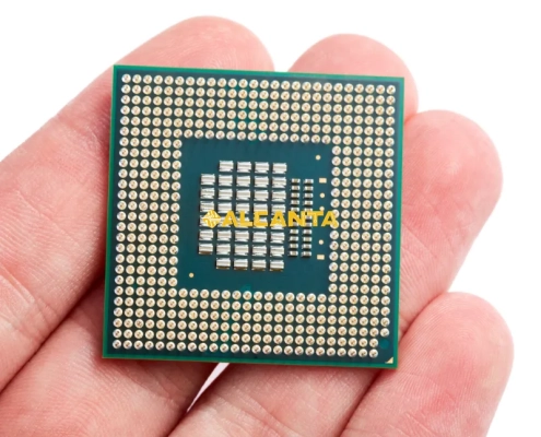
PLCC Packages: Enhancing Connectivity in Electronic Designs

In the dynamic realm of electronics, PLCC, or Plastic Leaded Chip Carrier, stands as a pivotal player. A compact, square-shaped package, PLCC encapsulates integrated circuits (ICs) with precision, featuring a configuration of pins that facilitates secure and efficient connection to circuit boards. Renowned for its versatility, PLCC plays a crucial role in the ever-evolving electronics industry. Its significance extends beyond its physical attributes; it serves as a linchpin for diverse applications, ranging from consumer electronics to industrial automation. With a robust design that aids in heat dissipation and compatibility with Surface Mount Technology (SMT), PLCC has become a cornerstone in modern circuit design. Let’s delve into the intricacies of PLCC packages, exploring their features, applications, and contributions to technological innovation.

Online Consultation or Need a Quote

PLCC Package Features

Physical Characteristics

  1. Size and Shape
    • PLCC packages are standardized, typically measuring 0.1 inches in pin pitch, ensuring compatibility across various applications.
    • The square shape of PLCC facilitates efficient use of PCB real estate, optimizing component layout for enhanced circuit integrity.
  2. Pin Configuration
    • With pin counts ranging from 20 to over 100, PLCC offers flexibility for diverse circuit designs, accommodating a spectrum of functionalities.
    • The pins are arranged in a circular pattern along the periphery, allowing for efficient and secure soldering onto the circuit board.
  3. Materials Used
    • PLCC packages are predominantly constructed from high-quality thermoplastics, ensuring not only mechanical strength but also resistance to environmental factors such as moisture and chemical exposure.
    • The materials used in PLCC production adhere to industry standards, providing a stable and reliable housing for integrated circuits.

Advantages of PLCC

  1. Heat Dissipation
    • PLCC’s square shape, coupled with its exposed leadframe, facilitates effective heat dissipation, preventing thermal issues in high-performance applications.
    • Enhanced thermal management ensures the longevity and reliability of integrated circuits, especially in demanding environments.
  2. Robustness and Durability
    • The robust encapsulation of PLCC packages shields the enclosed IC from mechanical stress, minimizing the risk of damage during handling and operation.
    • This durability is a crucial aspect, contributing to the overall ruggedness of electronic devices across industries.
  3. SMT (Surface Mount Technology) Compatibility
    • PLCC packages are designed for seamless integration into Surface Mount Technology processes, streamlining manufacturing workflows.
    • The flat leads of PLCC facilitate accurate placement on the PCB, enhancing the efficiency and precision of the assembly process.

PLCC packages offer a harmonious blend of meticulous physical characteristics and inherent advantages, making them a cornerstone in contemporary electronics manufacturing.

PLCC vs. LCC: Understanding the Differences

 Definition and Characteristics of LCC

  1. Definition
    • LCC, or Leadless Chip Carrier, represents an alternative packaging solution to PLCC, characterized by a lack of external leads.
    • LCC packages utilize a flat bottom surface for direct mounting onto the PCB, eliminating the need for traditional protruding leads.
  2. Characteristics
    • LCC packages often feature a compact, square or rectangular shape, contributing to a smaller footprint on the circuit board.
    • The absence of external leads simplifies the design and allows for higher pin densities, making LCC ideal for miniaturized and space-constrained applications.

Comparative Analysis

  1. Size and Form Factor
    • PLCC packages are generally larger due to the presence of external leads, making them more suitable for applications where space constraints are less critical.
    • LCC, being leadless, offers a more compact form factor, catering to designs emphasizing miniaturization and reduced PCB space.
  2. Pin Count and Arrangement
    • PLCC packages support a wide range of pin counts, typically arranged in a circular pattern around the package perimeter.
    • LCC packages, with their leadless design, can accommodate a higher pin density, as the pins are distributed across the entire bottom surface in a grid pattern.
  3. Use Cases and Industry Preferences
    • PLCC finds favor in applications where a balance between size and ease of manufacturing is crucial, such as industrial control systems and automotive electronics.
    • LCC is preferred in scenarios demanding high pin counts, miniaturization, and advanced technologies, including mobile devices, wearables, and other compact electronic gadgets.

While PLCC and LCC share some commonalities, their differences in size, pin configuration, and industry applications make each packaging type suitable for specific electronic design requirements. Designers must weigh these factors carefully to choose the optimal package for their intended application.

Popular IC Packages: Beyond PLCC

BGA Packages

  1. Definition and Characteristics
    • BGA, or Ball Grid Array, is a packaging solution characterized by an array of solder balls arranged on the underside of the package.
    • The compact, spherical design allows for a higher pin count and facilitates efficient heat dissipation, making BGAs suitable for high-performance applications.
  2. Applications in Modern Electronics
    • BGAs are widely utilized in modern electronics, particularly in applications where miniaturization and high-density interconnects are critical.
    • Common applications include microprocessors, graphic processors, and memory devices in consumer electronics like smartphones, tablets, and gaming consoles.

QFP Packages

  1. Overview and Features
    • QFP, or Quad Flat Package, is a surface-mount integrated circuit package featuring a rectangular or square shape.
    • QFP packages have pins extending from all four sides, providing a balance between pin count and ease of manufacturing.
  2. Use Cases in Circuit Design
    • QFP packages are versatile and find application in various electronic systems, including microcontrollers, programmable logic devices, and communication devices.
    • Their ease of manufacturing and relatively larger footprint compared to BGAs make QFPs suitable for designs where a compromise between size and pin count is essential.

Comparative Analysis with PLCC

  • While PLCC, BGA, and QFP packages all play crucial roles in electronics, the choice often depends on specific design requirements.
  • PLCC is preferred for applications where a balance of size and ease of manufacturing is essential.
  • BGA excels in miniaturized, high-performance applications with a focus on thermal management.
  • QFP strikes a middle ground, offering a reasonable pin count and ease of manufacturing.

In conclusion, understanding the features and applications of BGA and QFP packages alongside PLCC provides designers with a toolkit to optimize their choice based on the unique demands of each electronic design. The diversity in IC packages reflects the dynamic nature of the electronics industry and the continual pursuit of innovation.

PLCC Sockets: Enhancing Connectivity

Definition and Purpose

PLCC sockets serve as essential connectors in electronic systems, providing a secure and removable interface for PLCC packages. Their primary purpose is to enhance flexibility during the development, testing, and maintenance phases of electronic circuits. By using PLCC sockets, engineers can easily replace or upgrade integrated circuits without the need for soldering, ensuring efficiency and reducing the risk of damaging the components or the circuit board.

Types of PLCC Sockets

  1. Zero Insertion Force (ZIF)
    • ZIF sockets feature a mechanism that allows the PLCC package to be inserted or removed with minimal force.
    • This design minimizes stress on both the socket and the PLCC package during installation or replacement, preventing potential damage.
  2. Low Insertion Force (LIF)
    • LIF sockets provide a slightly more secure fit than ZIF sockets, requiring a low but still manageable level of force for PLCC package insertion.
    • LIF sockets offer a good compromise between ease of use and maintaining a stable connection.

Benefits and Considerations

  • Ease of Maintenance
    • PLCC sockets simplify maintenance procedures by enabling the quick replacement of integrated circuits without the need for desoldering or reworking the PCB.
    • This ease of maintenance reduces downtime during repairs and upgrades.
  • Testing and Prototyping
    • PLCC sockets are invaluable during the testing and prototyping stages of electronic design, allowing engineers to interchange components easily for experimentation and validation.
    • They facilitate a more agile development process, promoting iterative testing and refinement.
  • Flexibility in Component Selection
    • PLCC sockets enable the use of various PLCC packages without the need for specific PCB configurations for each component.
    • Designers can experiment with different ICs within the same socket, promoting adaptability in circuit design.
  • Considerations
    • While PLCC sockets offer numerous advantages, it’s crucial to consider factors such as contact reliability and the potential for signal degradation over time.
    • The additional height introduced by the socket must be considered in applications with strict space constraints.

In conclusion, PLCC sockets play a pivotal role in enhancing connectivity and flexibility in electronic systems. Their varied designs, including ZIF and LIF types, cater to different application needs, making them indispensable for efficient circuit development, testing, and maintenance. Designers must carefully weigh the benefits and considerations to choose the most suitable PLCC socket for their specific requirements.

PLCC IC Package Styles

Full Name and Abbreviation

PLCC, or Plastic Leaded Chip Carrier, encompasses various package styles that cater to diverse electronic design needs. Each style is identified by its unique features and specifications, contributing to the adaptability of PLCC packages in different applications.

Industry Standards

  1. JEDEC Standards
    • PLCC adheres to industry standards established by the Joint Electron Device Engineering Council (JEDEC).
    • These standards define the physical dimensions, pin configurations, and materials used in PLCC packages, ensuring compatibility and interchangeability across manufacturers.
  2. ISO Certification
    • Many PLCC manufacturers adhere to International Organization for Standardization (ISO) quality management standards.
    • ISO certification ensures that PLCC packages meet stringent criteria for reliability, performance, and consistency, instilling confidence in their use across various industries.

Trends and Innovations

  1. Miniaturization
    • Ongoing trends in the electronics industry drive the miniaturization of components, influencing PLCC designs to become more compact without compromising functionality.
    • Miniaturized PLCC styles cater to the growing demand for smaller and lighter electronic devices.
  2. Enhanced Thermal Management
    • Innovations in PLCC designs focus on improving thermal management capabilities to address the heat generated by advanced integrated circuits.
    • Styles with enhanced heat dissipation properties contribute to the reliability and longevity of electronic systems.
  3. High-Speed Signal Integrity
    • With the increasing demand for high-speed data transmission, certain PLCC styles incorporate features to maintain signal integrity and minimize electromagnetic interference.
    • Improved signal pathways and materials contribute to enhanced performance in applications requiring high-speed communication.
  4. Customization and Specialized Designs
    • Manufacturers offer customization options, allowing designers to tailor PLCC packages to specific application requirements.
    • Specialized PLCC styles cater to niche industries, providing solutions for unique challenges in fields such as aerospace, medical devices, and telecommunications.

Understanding the evolving landscape of PLCC IC package styles is crucial for staying abreast of industry advancements. As technology progresses, these trends and innovations continue to shape PLCC designs, ensuring their relevance and effectiveness in an ever-changing electronics ecosystem.

PLCC Package Cost Factors

Influencing Elements

  1. Materials
    • The choice of materials significantly impacts the cost of PLCC packages. High-quality thermoplastics with superior mechanical and thermal properties may incur higher costs.
    • Advanced materials designed to meet specific industry standards, such as those offering enhanced resistance to environmental factors, can contribute to increased costs.
  2. Manufacturing Complexity
    • The complexity of manufacturing processes plays a pivotal role in determining the overall cost of PLCC packages.
    • Advanced manufacturing techniques, precision in leadframe assembly, and additional features such as specialized coatings or unique pin configurations may raise production costs.
  3. Market Demand
    • Market demand directly influences the economies of scale in PLCC production. Higher demand often leads to increased production efficiency and lower per-unit manufacturing costs.
    • Conversely, limited demand for specific PLCC styles or customizations may result in higher costs due to reduced production volume.

Cost Considerations in Detail

  1. Materials Selection
    • Premium-grade thermoplastics that ensure durability and environmental resistance contribute to higher material costs.
    • Some PLCC styles may incorporate special materials for improved thermal management, adding to the overall cost.
  2. Manufacturing Processes
    • Precision in leadframe assembly, which includes the attachment of the integrated circuit to the package, is a critical factor.
    • Advanced techniques, such as automated assembly and inspection processes, may increase manufacturing complexity and, subsequently, costs.
  3. Customization and Features
    • PLCC packages with customization options or additional features, such as specific pin configurations or coatings, may involve more intricate manufacturing processes.
    • Specialized designs tailored to meet industry-specific requirements may result in higher costs due to the need for precision and attention to detail.
  4. Market Dynamics
    • Market demand for particular PLCC styles influences pricing dynamics.
    • High demand for standard PLCC configurations may result in competitive pricing, while limited demand for specialized styles may lead to higher costs to compensate for lower production volume.

Understanding these cost factors is essential for designers and manufacturers when selecting PLCC packages for their applications. Balancing cost considerations with the specific requirements of the electronic system ensures an optimal choice that aligns with both budget constraints and performance expectations.

FAQs About PLCC Packages

A PLCC (Plastic Leaded Chip Carrier) package is a type of integrated circuit (IC) packaging that encases the IC in a square or rectangular plastic housing. It features leads extending from each side for connection to a printed circuit board.

An LCC (Leadless Chip Carrier) package is another type of IC packaging, distinct from PLCC, characterized by a flat bottom surface without protruding leads. LCC packages often feature a compact shape, allowing for high pin density.

PLCC packages serve as protective enclosures for integrated circuits, providing a standardized form for easy installation on printed circuit boards. They offer physical protection to the enclosed IC and ensure secure electrical connections through the leads.

The primary difference lies in their physical design. PLCC packages have leads extending from the sides, facilitating easy soldering to a circuit board, while LCC packages have a leadless design with a flat bottom surface. LCCs often allow for higher pin density and are favored in miniaturized applications.