
Flex PCB Manufacturing Process: Step-by-Step Guide
Flexible printed circuit boards (Flex PCBs or FPCs) are essential components in modern electronics, offering compact size, lightweight design, and exceptional flexibility. Unlike rigid PCBs, FPCs can bend, fold, and twist to fit into complex device geometries, making them ideal for smartphones, wearable devices, medical equipment, and automotive electronics. Rigid-flex PCBs combine both rigid and flexible sections, enabling high-density connections where space is limited.
Flex PCBs provide design freedom but require precise manufacturing techniques to ensure reliability and durability. Understanding the materials, process flow, and limitations is key to designing and producing high-quality flexible circuits.
Raw Materials for Flex PCB
High-performance flex PCBs rely on specialized materials:
-
Flexible substrates: The backbone of an FPC is usually polyimide (PI) or polyethylene terephthalate (PET). PI is preferred for high-temperature and high-reliability applications.
-
Conductive materials: Copper foil, either rolled-annealed (RA) or electrodeposited (ED), forms the electrical traces.
-
Adhesives: Acrylic, epoxy, or polyimide adhesives bond copper to the flexible substrate, influencing thermal stability and mechanical reliability.
-
Coverlay and solder mask: Polyimide coverlay or flexible solder masks protect the circuit while maintaining flexibility.
-
Stiffeners and protective coatings: Reinforce areas where connectors are mounted or mechanical stress is concentrated.
Material choice directly impacts FPC performance, including bending endurance, heat resistance, and electrical reliability.
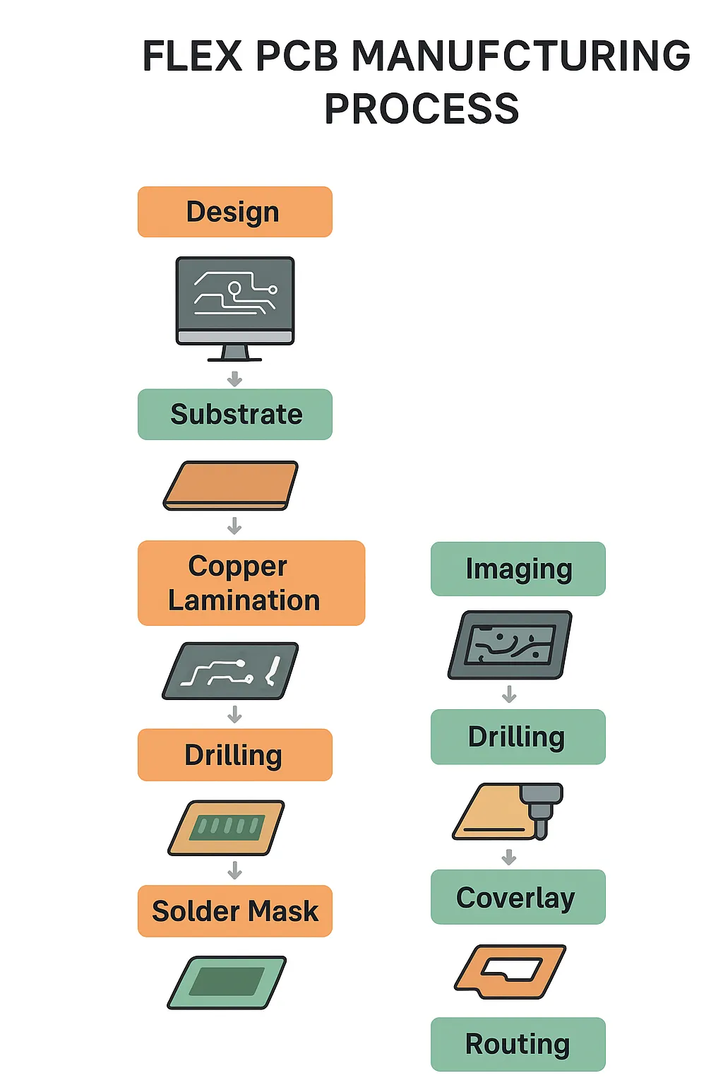
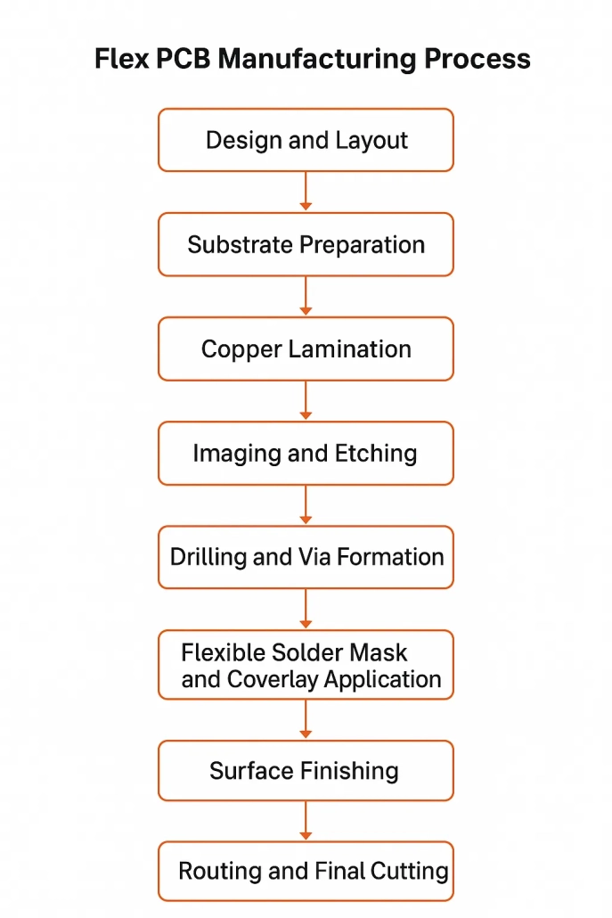
Flex PCB Manufacturing Process Flow
The fabrication of a flex PCB involves multiple precise steps:
1. Design and Layout
-
Circuit layout must consider bending zones, fold lines, and mechanical stress.
-
CAD software is used to create a design optimized for flexibility and connectivity.
2. Substrate Preparation
-
Polyimide film is cleaned and laminated with an adhesive to form the base layer.
3. Copper Lamination
-
Copper foil is laminated onto the substrate using roll lamination or dry film lamination.
-
Adhesion quality is critical to prevent delamination during bending.
4. Imaging and Etching
-
Photolithography defines circuit patterns.
-
Chemical etching removes unwanted copper, leaving precise traces.
5. Drilling and Via Formation
-
Laser or mechanical drilling creates through-holes or micro-vias.
-
Metallization ensures electrical connectivity across layers.
6. Flexible Solder Mask and Coverlay Application
-
Polyimide coverlay or flexible solder mask is applied to protect circuits.
-
Laminated coverlay is usually bonded with heat and pressure.
7. Surface Finishing
-
Finishes such as HASL, ENIG, or immersion silver enhance solderability.
-
The choice of finish depends on device reliability and assembly requirements.
8. Electrical Testing
-
Continuity, isolation, and functional tests verify the integrity of the circuit.
9. Routing and Final Cutting
-
Circuits are cut into final shapes using mechanical or laser routing.
-
Stiffeners are added to high-stress areas, such as connector pads.
Get a Quotation For Flex PCB Manufacturing Process Now
Rigid-Flex PCB Manufacturing
Rigid-flex PCBs integrate rigid and flexible layers, combining the durability of rigid boards with the adaptability of flex circuits. The manufacturing process requires additional steps:
-
Laminating rigid substrates with flexible layers.
-
Ensuring precise alignment between rigid and flexible sections.
-
Performing thermal and mechanical stress analysis to prevent failure during bending.
Rigid-flex PCBs are widely used in aerospace, medical devices, and high-density compact electronics.
Disadvantages of Flex PCB
While FPCs offer remarkable advantages, they also have limitations:
-
Higher manufacturing cost: Flex PCBs are more expensive than standard rigid PCBs due to materials and specialized processes.
-
Design complexity: Requires careful layout and stress analysis.
-
Mechanical stress sensitivity: Repeated bending can lead to cracks or trace failure.
-
Layer limitations: High-layer-count designs are more challenging compared to rigid PCBs.
Understanding these disadvantages helps engineers design reliable FPCs and avoid common failures.
Get a Quotation For Flex PCB Manufacturing Process Now
Key Considerations in Flex PCB Design and Manufacturing
-
Bending radius: Design for minimum bending stress to extend lifespan.
-
Thermal and mechanical management: Consider heat and repeated movement.
-
Material compatibility: Ensure adhesive, substrate, and copper are compatible for high-reliability applications.
-
Layer selection: Single-sided, double-sided, or multilayer FPCs depend on circuit complexity.
Get a Quotation For Flex PCB Manufacturing Process Now
Summary and Best Practices
Producing high-quality flex PCBs involves careful selection of materials, precise fabrication steps, and thorough testing. Following best practices in design and manufacturing ensures circuits that are reliable, durable, and capable of handling demanding applications. Working with experienced manufacturers familiar with flex and rigid-flex processes is crucial for optimal results.

